Problem: my K2 IND system Z axis is painful to move (ie focus on chips). The original servo drive relies on a computer controlled rotary switch for user focusing. This would take a bit of work to setup and I had problems getting the servo working reliably. I'm fairly certain I just need to buffer the encoder signals, but at this point I just want to KISS.
My first solution was to use a power drill but that was a bit messy.
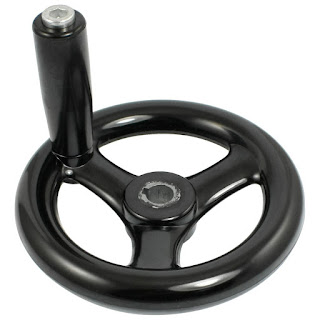
Lets do something a bit more proper. I selected a handwheel off of Amazon to replace the motor and bought some 1" aluminum stock to make an adapter. The stock needs two critical cuts:
- Outside diameter 0.472" to fit the wheel
- Inside diameter 0.5" to fit the microscope
Microscope diameter
I put the stock into my lathe and quickly re-discovered why I don't use the three jaw chuck: it has trouble holding material even when tightly clamped.
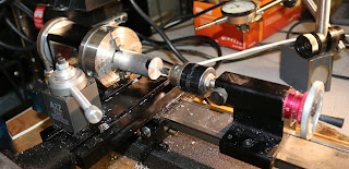
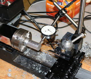
So I switched to a four jaw chuck and centered it using a dial indicator (sort of visible at right).
Its generally easier to clamp large parts, so lets make the inner diameter cut first so that, when its flipped around, its easier to hold.
First I center drilled the stock
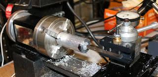
Then drilled it out as large as I could. This is quicker than using a lathe tool and allows the lathe tool to actually fit inside.
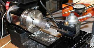
Now I switched to a tool bit to set the final diameter. I cut it to about 0.505" so that it slides on easily but is still pretty well centered.
I used calipers to check the size as I went. After some cutting the hole is correctly sized.
Microscope set screw
The microscope side has a large flat, so a set screw is a good choice to hold it in place.
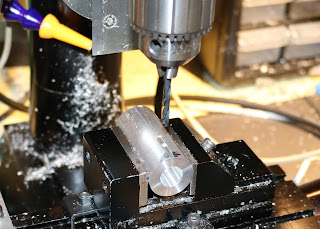
I started by clamping it in my milling machine and milling a flat so that I could drill a hole more precisely.
Next I used a center drill to start the hole.
10-32 seemed a good size so I selected a #21 drill bit and had at it
And tapping (carefully!)
Crank wheel diameter
Although the crank wheel has a key, I figured it would be simpler to press fit it on. So my plan was to machine it to very close tolerance and press it on.Re-attaching to the lathe and centering.
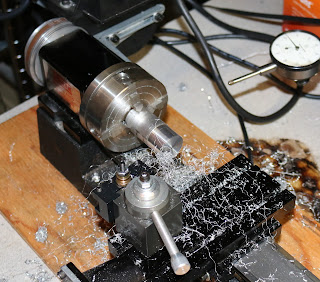
Starting to cut
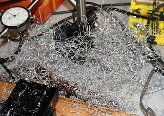
Lots of cutting!
Due to a measurement error (maybe overshot during finishing?) it was a close fit but not snug. Do I need to scrap the part or can I recover?
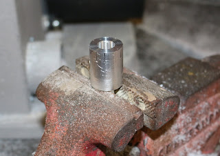
Its pretty close. Maybe I can squeeze it in my vice? Hmm no...wasn't enough.
Lets get something with a little more oomph.
Seems to have done the trick.
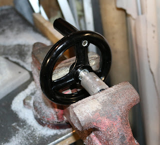
Tried to press it directly but it was clear it was going to go off center.
So I added some supports.
Which did the job.
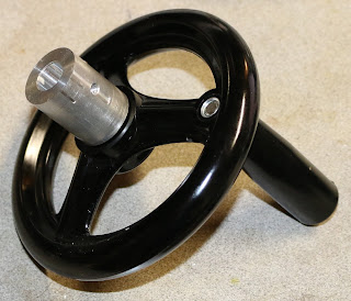
Viola! Everything fit together as expected and the crank turns smoothly. Now I can easily focus on ICs and not have to use frustrating hacks to use the microscope.














No comments:
Post a Comment